

Harmonic reducer principle
20 Century 5 0 American genius inventor C. in the 1900s Walt Musser invented harmonic drive, which transmits power load through the fluctuation of flexible thin-walled parts.
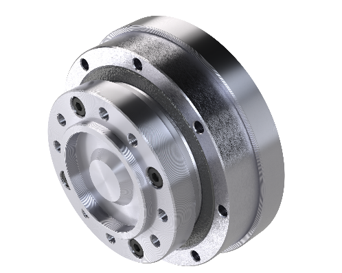
The most basic components of a harmonic reducer include three parts: rigid wheel, flexible wheel, and wave generator.
1、 Rigid wheel: A rigid inner gear ring, generally two more teeth than the flexible wheel. Usually fixed to the housing.
2、 Flexible wheel: A thin-walled metal elastic component with gears on the outer circumference of the opening, which periodically deforms with the rotation of the wave generator. Usually connected to the output shaft.
3、 Wave generator: Consists of an elliptical cam and a flexible bearing, usually connected to the input shaft. The inner ring of the flexible bearing is fixed to the cam, and the outer ring is elastically deformed into an ellipse through rolling balls.
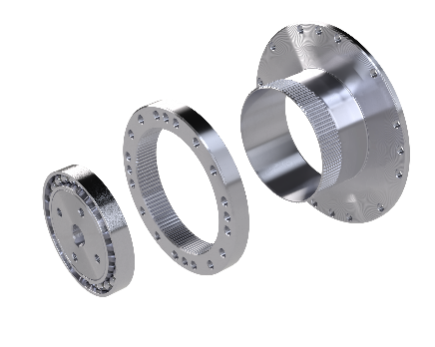
Wave generator Rigid wheel Flexible wheel
Characteristics of harmonic reducer:
1、 High load capacity With the same reduction ratio and gearbox size, the load capacity is higher than that of traditional reducers because the meshing between the teeth of the harmonic is surface contact, and the number of teeth meshing simultaneously is relatively large.
2、 Large transmission ratio The single-stage transmission ratio can be i=50~ 300.
3、 Light weight Because its core component for transmitting torque is the flexible wheel, which is a thin-walled part, its weight is relatively light.
4、 Stable transmission Low impact, noise, and high transmission accuracy. The multi-tooth meshing characteristics of the harmonic reducer make its operation stable and the transmission accuracy high (generally, the transmission error is less than 1 arcmin).
High torque, long life
Through theoretical design analysis and experimental verification, multiple iterations of optimization. Performance directly benchmarks the latest generation of high-torque products from well-known foreign brands.
Low vibration, high precision
Through in-depth research on the mechanism of harmonic transmission, starting from vibration transmission, the vibration problem of the harmonic reducer is solved from the excitation source and the transmission process.
High efficiency, low backlash
By optimizing the tooth surface meshing marks and creating an isovolumetric tooth profile with multiple meshing points, the tooth surface friction is reduced.
LXC series naming rules and performance
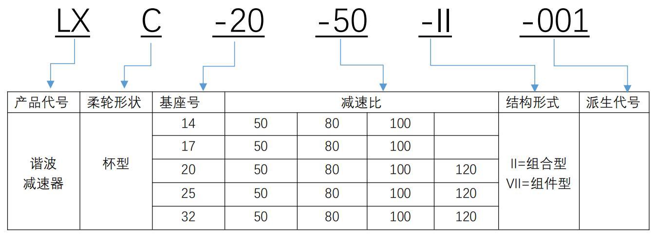
LX —— Represents Lianyi harmonic reducer.
C —— Indicates that the flexible wheel is in the shape of a teacup.
-2 0 —— Indicates that the pitch circle diameter of the reducer gear is 5 0 (2 0*2.54) mm.
-5 0 —— Indicates that the reduction ratio of the reducer is 1:5 0 (reduction ratio when the wave generator is input, the rigid wheel is fixed, and the flexible wheel is output).
-II —— Represents the structural form of the reducer. Refer to the model details for detailed parameters.
-0 01 —— Represents the derivative code of the reducer, in which some structures are modified from the standard model.
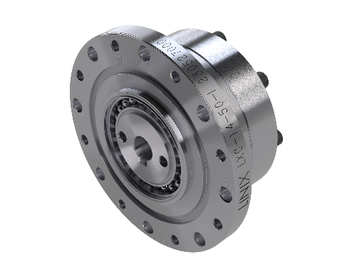
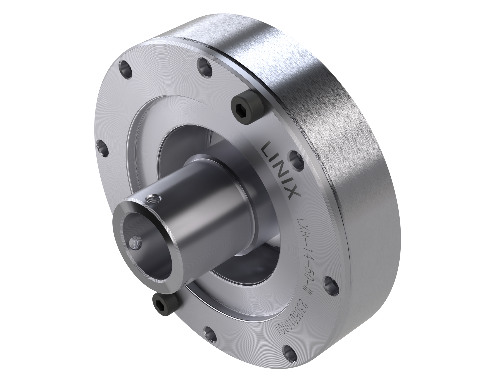
LXC-II model
The LXC-II series reducer is a simple combined reducer with a separated wave generator and reducer body. Customers need to design and fix the wave generator axially and radially, and add lubricating grease to the overall cavity. The installation requirements are high, but the overall structure can be made more compact. Its wave generator can be directly installed on the motor shaft, generally used in end transmission mechanisms.
|
LXC- XX - XXX -II series performance parameters table |
|||||||||
|
Model |
Reduction ratio |
Rated torque *1 (Nm) |
Maximum allowable torque for starting and stopping (Nm) |
Maximum allowable average load torque *2 (Nm) |
Instantaneous maximum allowable torque *3 (Nm) |
Maximum allowable input speed |
Allowable average input speed |
Backlash |
Transmission error |
|
≤ |
≤ |
||||||||
|
14 |
50 |
7 |
23 |
9 |
46 |
8000 |
3500 |
10 |
60 |
|
80 |
10 |
30 |
14 |
51 |
10 |
60 |
|||
|
100 |
10 |
36 |
14 |
70 |
10 |
60 |
|||
|
17 |
50 |
21 |
44 |
34 |
91 |
7000 |
3500 |
10 |
60 |
|
80 |
29 |
56 |
35 |
113 |
10 |
60 |
|||
|
100 |
31 |
70 |
51 |
143 |
10 |
60 |
|||
|
20 |
50 |
33 |
73 |
44 |
127 |
6000 |
3500 |
10 |
60 |
|
80 |
44 |
96 |
61 |
165 |
10 |
60 |
|||
|
100 |
52 |
107 |
64 |
191 |
10 |
60 |
|||
|
120 |
52 |
113 |
64 |
191 |
10 |
60 |
|||
|
25 |
50 |
51 |
127 |
72 |
242 |
5500 |
3500 |
10 |
60 |
|
80 |
82 |
178 |
113 |
332 |
10 |
60 |
|||
|
100 |
87 |
204 |
140 |
369 |
10 |
60 |
|||
|
120 |
87 |
217 |
140 |
395 |
10 |
60 |
|||
|
32 |
50 |
99 |
281 |
140 |
497 |
4500 |
3500 |
10 |
60 |
|
80 |
153 |
395 |
217 |
738 |
10 |
60 |
|||
|
100 |
178 |
433 |
281 |
841 |
10 |
60 |
|||
|
120 |
178 |
459 |
281 |
892 |
10 |
60 |
|||
|
*1 The size of the rated torque when the rated speed is 2000 rpm. |
|||||||||


LXH Series Naming Rules and Performance
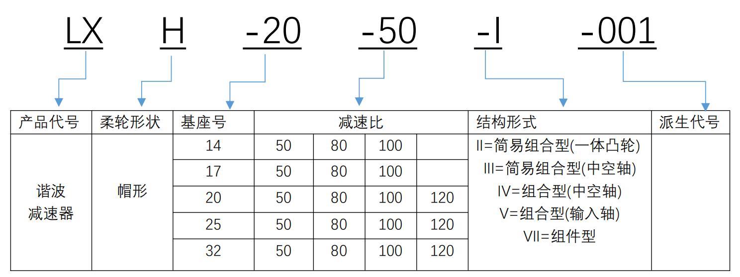
LX —— Represents Lianyi harmonic reducer.
H ——Indicates that the flexible wheel is in the shape of a top hat.
-2 0 —— Indicates that the pitch circle diameter of the reducer gear is 5 0 (2 0*2.54) mm.
-5 0 —— Indicates that the reduction ratio of the reducer is 1:5 0 (reduction ratio when the wave generator is input, the rigid wheel is fixed, and the flexible wheel is output).
-I —— Represents the structural form of the reducer. Refer to the model details for detailed parameters.
-0 01 —— Represents the derivative code of the reducer, in which some structures are modified from the standard model.
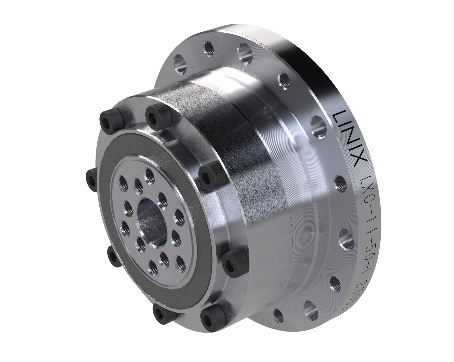
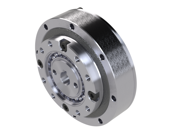
LXH- II Series Speed Reducer
The LXH--II series speed reducer is a simple combination type speed reducer with a separated wave generator and reducer body. Customers need to design and fix the wave generator axially and radially, and add grease to the overall cavity later. The installation requirements are high, but the overall structure can be made more compact. Its wave generator can be directly installed on the motor shaft, generally used in end drive mechanisms.
|
LXH- XX - XXX -II series performance parameters table |
|||||||||
|
Model |
Reduction ratio |
Rated torque *1 (Nm) |
Maximum allowable torque for starting and stopping (Nm) |
Maximum allowable average load torque *2 (Nm) |
Instantaneous maximum allowable torque *3 (Nm) |
Maximum allowable input speed |
Allowable average input speed |
Backlash |
Transmission error |
|
≤ |
≤ |
||||||||
|
14 |
50 |
7 |
23 |
9 |
46 |
8000 |
3500 |
10 |
60 |
|
80 |
10 |
30 |
14 |
51 |
10 |
60 |
|||
|
100 |
10 |
36 |
14 |
70 |
10 |
60 |
|||
|
17 |
50 |
21 |
44 |
34 |
91 |
7000 |
3500 |
10 |
60 |
|
80 |
29 |
56 |
35 |
113 |
10 |
60 |
|||
|
100 |
31 |
70 |
51 |
143 |
10 |
60 |
|||
|
20 |
50 |
33 |
73 |
44 |
127 |
6000 |
3500 |
10 |
60 |
|
80 |
44 |
96 |
61 |
165 |
10 |
60 |
|||
|
100 |
52 |
107 |
64 |
191 |
10 |
60 |
|||
|
120 |
52 |
113 |
64 |
191 |
10 |
60 |
|||
|
25 |
50 |
51 |
127 |
72 |
242 |
5500 |
3500 |
10 |
60 |
|
80 |
82 |
178 |
113 |
332 |
10 |
60 |
|||
|
100 |
87 |
204 |
140 |
369 |
10 |
60 |
|||
|
120 |
87 |
217 |
140 |
395 |
10 |
60 |
|||
|
32 |
50 |
99 |
281 |
140 |
497 |
4500 |
3500 |
10 |
60 |
|
80 |
153 |
395 |
217 |
738 |
10 |
60 |
|||
|
100 |
178 |
433 |
281 |
841 |
10 |
60 |
|||
|
120 |
178 |
459 |
281 |
892 |
10 |
60 |
|||
|
*1 The size of the rated torque when the rated speed is 2000 rpm. |
|||||||||


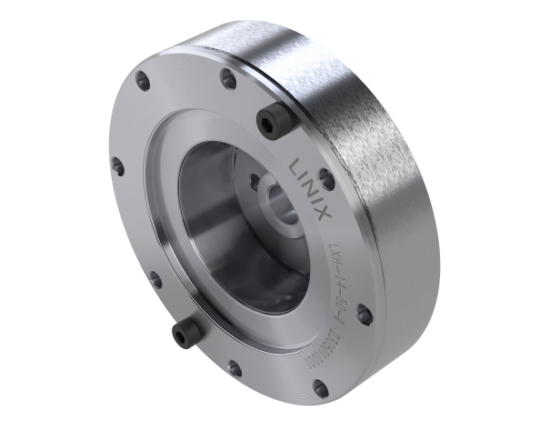
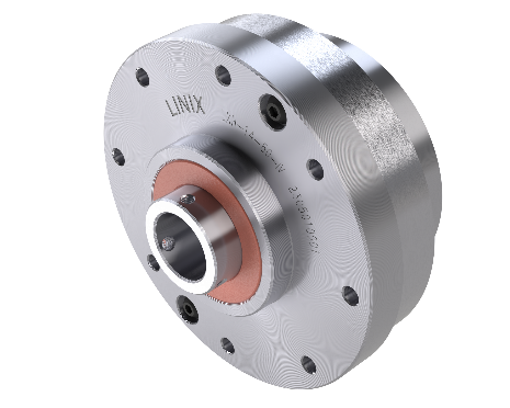
LXH-- III Series Speed Reducer
The LXH-III series speed reducer is a simple combination type speed reducer with a separated wave generator and reducer body. Customers need to design and fix the wave generator axially and radially, and add grease to the overall cavity later. The installation requirements are high, but the overall structure can be made more compact. Its wave generator is hollow, allowing for hollow wiring, and is generally used in intermediate drive mechanisms.
|
LXH-III Series Performance Parameters Table |
|||||||||
|
Model |
Reduction ratio |
Rated torque *1 (Nm) |
Maximum allowable torque for starting and stopping (Nm) |
Maximum allowable average load torque *2 (Nm) |
Instantaneous maximum allowable torque *3 (Nm) |
Maximum allowable input speed |
Allowable average input speed |
Backlash |
Transmission error |
|
≤ |
≤ |
||||||||
|
14 |
50 |
7 |
23 |
9 |
46 |
8000 |
3500 |
10 |
60 |
|
80 |
10 |
30 |
14 |
51 |
10 |
60 |
|||
|
100 |
10 |
36 |
14 |
70 |
10 |
60 |
|||
|
17 |
50 |
21 |
44 |
34 |
91 |
7000 |
3500 |
10 |
60 |
|
80 |
29 |
56 |
35 |
113 |
10 |
60 |
|||
|
100 |
31 |
70 |
51 |
143 |
10 |
60 |
|||
|
20 |
50 |
33 |
73 |
44 |
127 |
6000 |
3500 |
10 |
60 |
|
80 |
44 |
96 |
61 |
165 |
10 |
60 |
|||
|
100 |
52 |
107 |
64 |
191 |
10 |
60 |
|||
|
120 |
52 |
113 |
64 |
191 |
10 |
60 |
|||
|
25 |
50 |
51 |
127 |
72 |
242 |
5500 |
3500 |
10 |
60 |
|
80 |
82 |
178 |
113 |
332 |
10 |
60 |
|||
|
100 |
87 |
204 |
140 |
369 |
10 |
60 |
|||
|
120 |
87 |
217 |
140 |
395 |
10 |
60 |
|||
|
32 |
50 |
99 |
281 |
140 |
497 |
4500 |
3500 |
10 |
60 |
|
80 |
153 |
395 |
217 |
738 |
10 |
60 |
|||
|
100 |
178 |
433 |
281 |
841 |
10 |
60 |
|||
|
120 |
178 |
459 |
281 |
892 |
10 |
60 |
|||
|
*1 The size of the rated torque when the rated speed is 2000 rpm. |
|||||||||


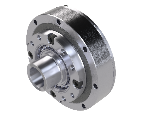
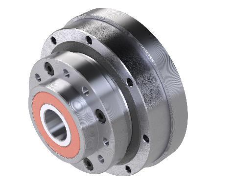
LXH-- IV Series Speed Reducer
The LXH--IV series speed reducer is a combination type speed reducer with a hollow input end. The grease and support bearings are integrated into the unit, making installation easier for customers. It allows for hollow wiring and is generally used in intermediate drive mechanisms.
|
LXH-IV Series Performance Parameters Table |
|||||||||
|
Model |
Reduction ratio |
Rated torque *1 (Nm) |
Maximum allowable torque for starting and stopping (Nm) |
Maximum allowable average load torque *2 (Nm) |
Instantaneous maximum allowable torque *3 (Nm) |
Maximum allowable input speed |
Allowable average input speed |
Backlash |
Transmission error |
|
≤ |
≤ |
||||||||
|
14 |
50 |
7 |
23 |
9 |
46 |
8000 |
3500 |
10 |
60 |
|
80 |
10 |
30 |
14 |
51 |
10 |
60 |
|||
|
100 |
10 |
36 |
14 |
70 |
10 |
60 |
|||
|
17 |
50 |
21 |
44 |
34 |
91 |
7000 |
3500 |
10 |
60 |
|
80 |
29 |
56 |
35 |
113 |
10 |
60 |
|||
|
100 |
31 |
70 |
51 |
143 |
10 |
60 |
|||
|
20 |
50 |
33 |
73 |
44 |
127 |
6000 |
3500 |
10 |
60 |
|
80 |
44 |
96 |
61 |
165 |
10 |
60 |
|||
|
100 |
52 |
107 |
64 |
191 |
10 |
60 |
|||
|
120 |
52 |
113 |
64 |
191 |
10 |
60 |
|||
|
25 |
50 |
51 |
127 |
72 |
242 |
5500 |
3500 |
10 |
60 |
|
80 |
82 |
178 |
113 |
332 |
10 |
60 |
|||
|
100 |
87 |
204 |
140 |
369 |
10 |
60 |
|||
|
120 |
87 |
217 |
140 |
395 |
10 |
60 |
|||
|
32 |
50 |
99 |
281 |
140 |
497 |
4500 |
3500 |
10 |
60 |
|
80 |
153 |
395 |
217 |
738 |
10 |
60 |
|||
|
100 |
178 |
433 |
281 |
841 |
10 |
60 |
|||
|
120 |
178 |
459 |
281 |
892 |
10 |
60 |
|||
|
*1 The size of the rated torque when the rated speed is 2000 rpm. |
|||||||||


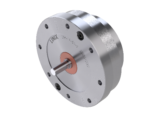
LXH-- V Series Speed Reducer
LXH --The V series speed reducer is a combination type speed reducer with a round shaft input end. The grease and support bearings are integrated into the unit, making installation easier for customers. It does not allow for hollow wiring and is generally used in end mechanisms.
|
LXH-V Series Performance Parameters Table |
|||||||||
|
Model |
Reduction ratio |
Rated torque *1 (Nm) |
Maximum allowable torque for starting and stopping (Nm) |
Maximum allowable average load torque *2 (Nm) |
Instantaneous maximum allowable torque *3 (Nm) |
Maximum allowable input speed |
Allowable average input speed |
Backlash |
Transmission error |
|
≤ |
≤ |
||||||||
|
14 |
50 |
7 |
23 |
9 |
46 |
8000 |
3500 |
10 |
60 |
|
80 |
10 |
30 |
14 |
51 |
10 |
60 |
|||
|
100 |
10 |
36 |
14 |
70 |
10 |
60 |
|||
|
17 |
50 |
21 |
44 |
34 |
91 |
7000 |
3500 |
10 |
60 |
|
80 |
29 |
56 |
35 |
113 |
10 |
60 |
|||
|
100 |
31 |
70 |
51 |
143 |
10 |
60 |
|||
|
20 |
50 |
33 |
73 |
44 |
127 |
6000 |
3500 |
10 |
60 |
|
80 |
44 |
96 |
61 |
165 |
10 |
60 |
|||
|
100 |
52 |
107 |
64 |
191 |
10 |
60 |
|||
|
120 |
52 |
113 |
64 |
191 |
10 |
60 |
|||
|
25 |
50 |
51 |
127 |
72 |
242 |
5500 |
3500 |
10 |
60 |
|
80 |
82 |
178 |
113 |
332 |
10 |
60 |
|||
|
100 |
87 |
204 |
140 |
369 |
10 |
60 |
|||
|
120 |
87 |
217 |
140 |
395 |
10 |
60 |
|||
|
32 |
50 |
99 |
281 |
140 |
497 |
4500 |
3500 |
10 |
60 |
|
80 |
153 |
395 |
217 |
738 |
10 |
60 |
|||
|
100 |
178 |
433 |
281 |
841 |
10 |
60 |
|||
|
120 |
178 |
459 |
281 |
892 |
10 |
60 |
|||
|
*1 The size of the rated torque when the rated speed is 2000 rpm. |
|||||||||


Previous:
: Next
Harmonic reducer
Share to:


Product Category:
Product Consultation
Submit your contact information, and we will contact you as soon as possible!
More Products


Address: No. 196, Industrial Avenue, Hengdian Town, Dongyang City, Zhejiang Province
Linix Motor South China Office
Address: Room 1003, Aoxing Science and Technology Park, No. 2, Tiansha Road, Dongguan City, Guangdong Province

E-mail:
TEL:
在线客服添加返回顶部
页面顺滑的滚动
启用全局默认滚动动画 (向上滚动)
右侧在线客服样式 1,2,3 2
图片alt标题设置: Linix Motor
CSS / JS 文件放置地